Call Us Toll Free:
877-233-2618
An Overhead Conveyor System offers many advantages in terms of the ability to transport products, pieces or parts in unused plant spaces above the work area….come down to places needed for loading or unloading….handle heavy loads and odd shaped items….incorporate cleaning, painting, heat treating, baking, or similar operations….and can be easily modified if production needs change. Use the links below to skip to a specific topic on this page.
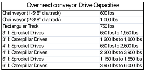
Overhead Conveyors have three basic capacities: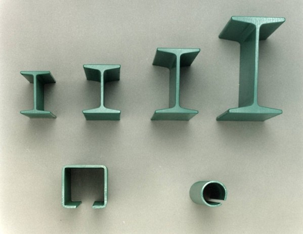
Overhead Conveyors come in three basic styles:
 |
 |
 |
 |
– Start with drawing a plan to scale of the building area in which the conveyor system will be installed, showing all aisles, columns, obstructions, equipment, and areas to be considered. – Determine the type of load carried.
Consider the size and type of load to be carried and also the type of carrier or hook to be used.
– Then consider the total load to be carried on each trolley.
This is an important factor in determining the size of the trolley, chain, track and drive to be used.
– Plan the material flow which involves the speed at which the conveyor will operate, and the spacing of trolleys, carriers or hooks.
The desired conveyor speed is calculated by taking the required number of parts per hour, multiplying this by the carrier spacing and dividing by 60 multiplied by the parts per carrier. Manual loading and unloading of an overhead conveyor is considered to be between 10 and 25 FPM.
– Consider the type of conditions under which the conveyor will operate.
This includes temperature, paint and chemical conditions and the accessibility for lubrication or other factors which would have important bearing on the type of components to be used especially the kind of trolleys, turns and bearings.
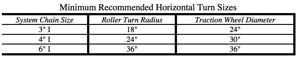
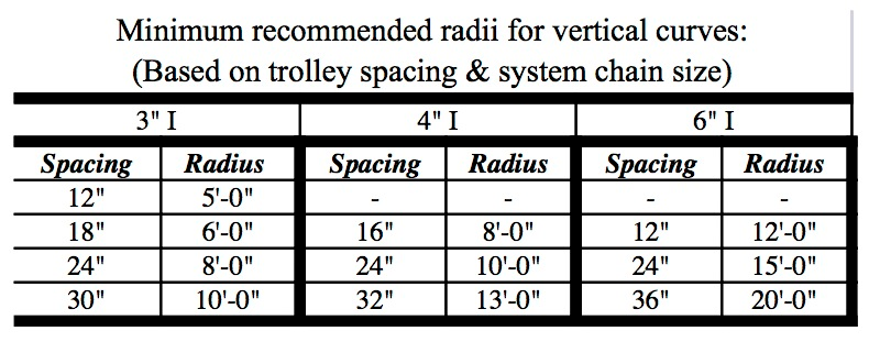
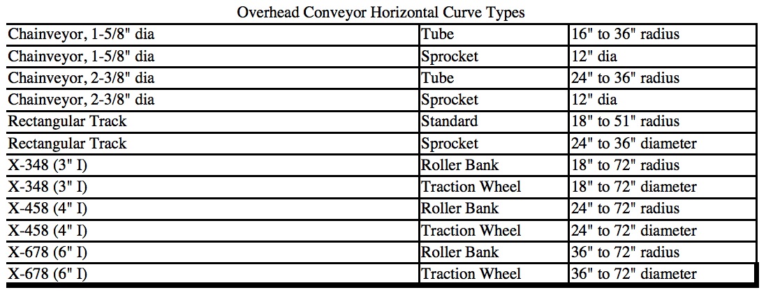
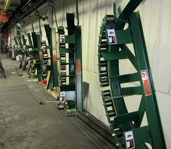
– Choose the horizontal and vertical curves based on the size of load and desired carrier spacing.
 |
|
 |
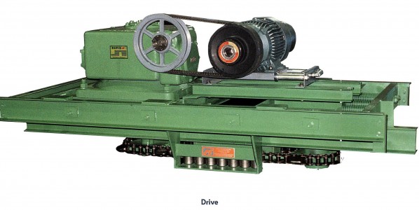
– Be sure that the loads do not interfere with each other in curves by laying out the horizontal and vertical curves and then laying in the loads. – Allow for one trolley spacing of straight track between horizontal and vertical changes to ensure proper chain alignment. – Try to place the drive in the high point in the system with the take-up in front of the drive preferably in the low point in the system, but close to the drive as possible.
This will ensure that slack chain is pulled away from the drive chain.
– Figure the total chain pull by first calculating the weight of the product, carrier, chain and attachments on the entire system.
The most practical thing to do is to provide an ample margin of safety in planning the chain and drive size.
– One means of figuring the total chain pull, particularly on simple systems involving only one drive is the Total Moving Load Method as described below:
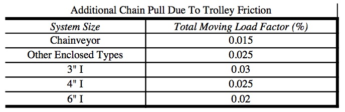
Calculate the total moving load and multiple this number by the friction factor from Table C. This will give you a quick chain pull to help choose a drive, system size, and type. To this figure you must add the vertical loads by adding and subtracting the up and down loads. Multiply the vertical drop or rise by the number of pounds per foot and consider the worst conditions of loading. Many times a load going up will be cancelled by a load going down.
|
|
 |
 |
|
Take-Up travel is normally 8”, 12” or 16” and amount of chain that can be taken up is double the travel.
The “X” number designation of I-beam conveyors is a combination of the chain pitch (3”,4” or 6”) and the diameter of the chain pin (.48”, .58”, or .68”)
 |
 |
 |
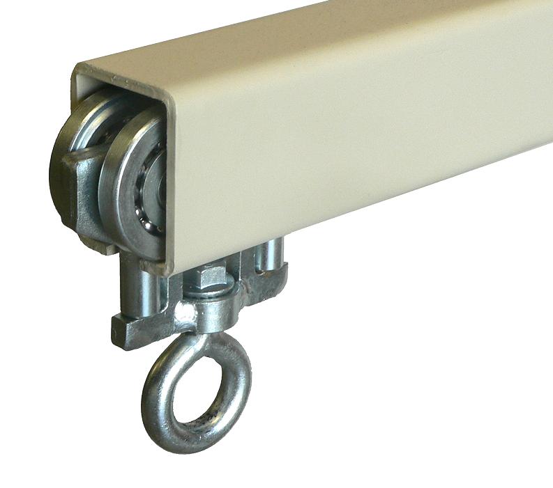
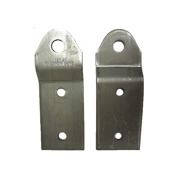
Trolleys for overhead conveyor systems come in many styles and types depending on the application and cost.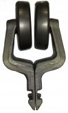 The brackets come in two styles:
The wheel connections come in two syles:
There are two basic choices for trolley wheels:
(There are special types of wheels such as thermoplastic wheels designed to resist cleaning solutions available in 3” I)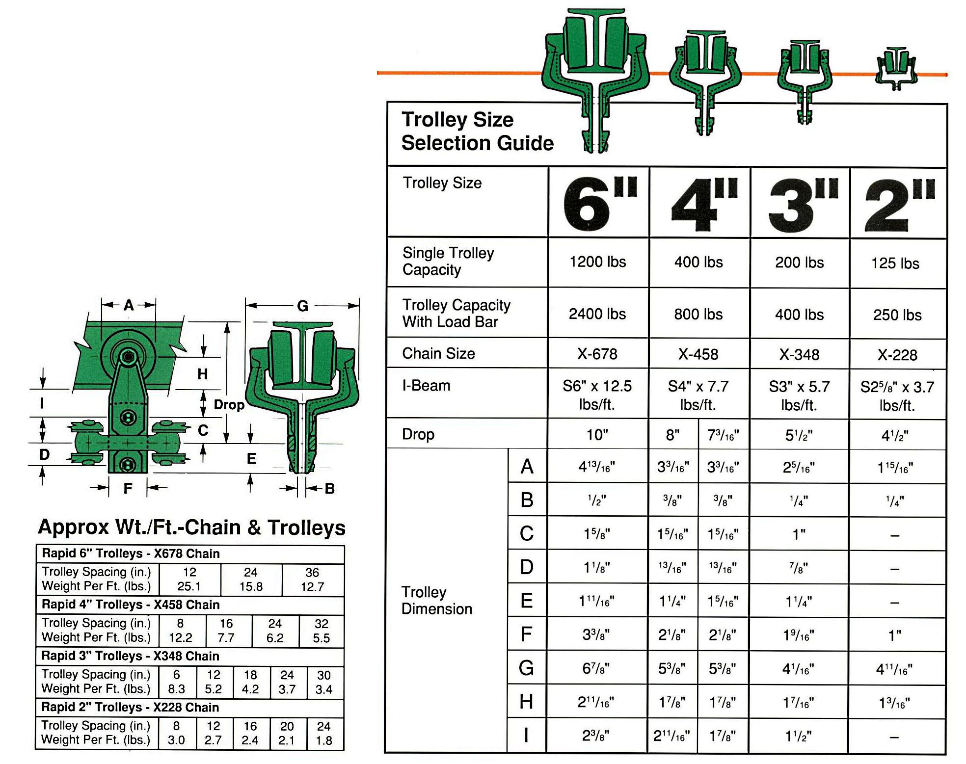
Attachments for overhead trolleys come in many varied sizes and types depending on the application and load.
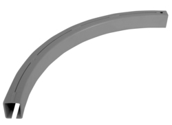
Load Bars: designed to connect two trolley brackets designed to negotiate around horizontal and vertical curves without binding. 
3”I load bar: 6” hole centers……500 lbs capacity
4”I load bar: 8” hole centers…..1000 lbs capacity
6”I load bar: 12” hole centers….2400 lbs capacity
1. H Attachments:(the most commonly used attachment)
 2. B Attachments:
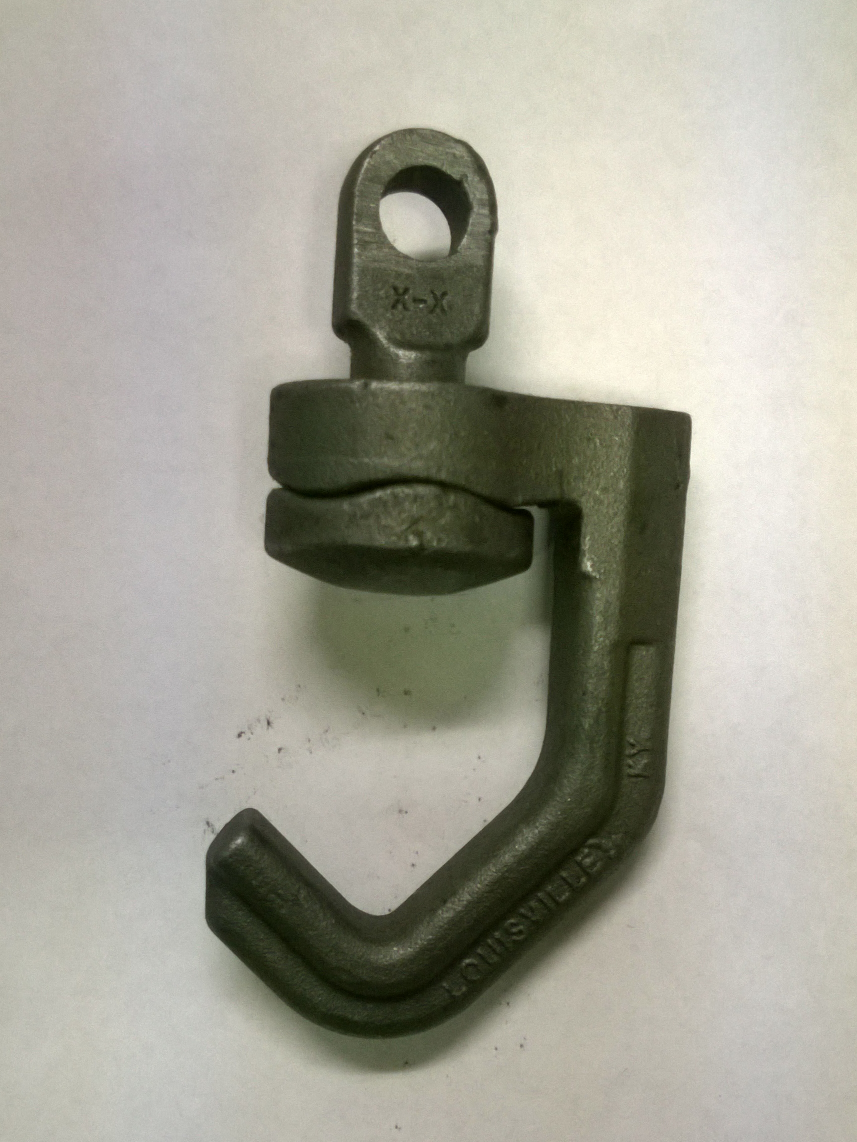
3. C Attachments:
4. I or “Dummy” attachments:
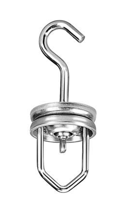
5. Indexing Swivels:
 |
90 degree indexing swivel hook type with detents at 90 degrees…has a 125 lb capacity and is used on 3”I and 4”I systems. | |
 |
90 degree star wheel indexing swivel which makes contact with stops along the travel of the system to rotate the swivel….has a 125 lb capacity and is used on 3”I and 4”I systems |
 |
6. Rotary Rack Swivel hooks have a gear rack which provides positive turning action when engaged by a corresponding gear
|
 |
7. Spinner hooks provide for continuous rotation when engaged by a fixed friction bar… Capacity is 50 lbs |
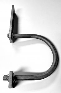 |
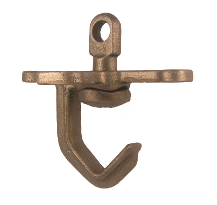
8. Sanitary hooks which have a “C” yoke to be used with a sanitary pan under the conveyor rail and trolleys. This is one we designed for a specific project. |
Anti-backup “uphill” safety devices for vertical curves in the event of chain breakage to prevent chain runaway.
Anti-runaway “downhill” safety devices for vertical curves. Involves a limit switch to cut the drive off and a mechanical device to stop the chain from running away in the case of chain breakage.
There are two basic styles to accommodate light, medium and heavy loads. These are used to provide protection from falling parts from the conveyor system.
Welded Wire Mesh Guarding: This is used for most light and medium loads.
Expanded Metal Guarding: This type is for heavier loads and is fabricated from structural steel to fit the application (more expensive)
1. When a system is beginning to exhibit problems – one pitfall is to fail to look at lubrication and dirty conditions as the cause.
2. When adding footage to a two drive system – one pitfall is to install new chain with old chain.
10’ of new chain may be 10’-3” long on old chain due to stretch (wear) which means the new and old chains are different pitches. 200’ of new chain would be 205’ of old chain and when the new section rotates to the opposite side of the drives the 205’ will become 200’ and the system take-up on that side will not be able to handle it causing damage to occur.
3. When replacing or adding new components to a 4”I system – one pitfall is to not realize that 4” I systems have two trolleys drops, 7-3/16” and 8”.
Trolley drop is the distance from the top of the track to the centerline of the chain. The trolley drop for 3” I is 5-1/2” and the drop for 6” I is 10”.
4. When making up chain – one pitfall is to not use the manufacturers trolley nuts and bolts.
The nuts and bolts are special with thin line locking nuts and exact length bolts.